Safety & Operating Manual.
Read before first use. Every operator should read, understand and refer to these instructions. Training from a qualified and competent rigging instructor is required.
Jump to a section
- 01Warnings & safety precautions
- 02Identification & WLL ratings
- 03Product life & inspection
- 04Package contents
- 05Parts identification
- 06Harken self-tailing winch
- 07Winch care & lubrication
- 08Stem mounting
- 09Horizontal anchoring
- 10Rope routing: bollard
- 11Rope routing: winch
- 12Double working lines
- 13Accessories & bollard care
- 14Support & service policy
- 15Records & inspection log
Warnings & safety precautions
Activities using this equipment are inherently dangerous. It is not possible to cover every eventuality relating to the use of this equipment. Purchasers and users of the HOLD FAST rigging device should seek professional training from a fully qualified and competent instructor prior to engaging in any activity. If you are not able, or not in a position to assume this responsibility, DO NOT use this product. The manufacturer, its distributors, and retailers do not accept any liability if users do not follow the instructions correctly. Only the techniques shown in the diagrams are authorized. Any other use deviating from those shown may result in serious injury or death.
Prior to each use a complete on-site risk assessment must be carried out to ascertain that the device is appropriate to the work being undertaken. The HOLD FAST rigging device must also be compatible with all other components within the rigging system.
Users must always ensure that all components of the rigging system are suitable for the foreseeable loadings that may be applied during use. Poor technique and shock loading may cause catastrophic failure of this equipment and should be avoided. Where a failure of the product may occur, a suitable backup system must be installed and used. All components must be inspected before and after each lowering/lifting operation. Retire the HOLD FAST from use if there are any tactile or visual signs of wear or damage.
Always use the correct rope diameter and never exceed the recommended maximum. Each component has a Working Load Limit (WLL), the maximum load that may be applied, whether lifting on the self-tailing winch or lowering on the fixed bollard. Values assume a static vertical load applied as specified here.
Safety rules
- The HOLD FAST rigging device must NEVER be used for lifting or lowering people. Neither the self-tailing winch nor the rigging bollard are intended or rated for use as Personal Protective Equipment (PPE).
- Always keep body parts, loose clothing, and debris away from the device when in use.
- Always use appropriate hand, head, and eye protection when operating the device.
- When holding the working line, NEVER wrap the line around your hands or other body parts. Always ensure it can run freely in case you need to release the line in an emergency.
- Do not stand at any time, or allow others to stand, directly under the load being lowered or under the work being performed above. Ensure all persons are operating from a safe distance.
- Any potential dynamic/shock loading must always be kept to an absolute minimum.
- All connecting devices or components must be retired from use if subjected to impact loading.
- To avoid damage to the device, minimize negative rigging fall distance within the system as much as possible.
- Always maintain control of each and every suspended load until it has safely reached the ground and has been untied.
- All moving parts must be lubricated regularly using suitable lubrication. Ensure no excess lubrication contacts any textile accessories or working line. Remove all excess lubrication immediately.
- Products covered under these instructions should never be resold or used by a third party after use by the original purchaser.
We recommend that all users of this equipment be given a copy of these instructions. They must read them, understand them, and explicitly follow all instructions and cautions. Any person using this equipment should be fully trained and competent in its use before carrying out any rigging operations.
Identification & WLL ratings
Identification & traceability
Each HOLD FAST unit carries an identification label on the back of the rigging plate. It shows the unit serial number and model designation (for example, 2645OG identifies serial 2645 of the OG model) together with a scannable QR code. Use this number when contacting the manufacturer about your product.
The label is mandatory. If it is missing, damaged or unreadable, contact Hold Fast Rigging for a replacement before returning the unit to service.
The QR code opens the asset page for your unit: the Quick Start Field Guide, this complete Safety & Operating Manual, and setup, operation, maintenance & storage videos. Also at holdfast-rigging.com.
Working Load Limit (WLL) ratings
The HOLD FAST rigging device must always be used with the correct diameter of rope. You must never exceed the recommended maximum rope diameters. Each device component has a Working Load Limit (WLL), the maximum load allowed to be applied to the device either for lifting via self-tailing winch or lowering on the fixed bollard. These values are based on a static vertical load applied as specified in these instructions.
| Model / component | Max rope diameter | Working Load Limit (WLL) |
|---|---|---|
| HOLD FAST OG: Bollard | 9/16" | 2,000 lbs |
| HOLD FAST XL: Bollard | 5/8" | 2,500 lbs |
| Harken Radial 20 ST Winch (OG) | 1/2" | 950 lbs |
| Harken Radial 40 ST Winch (XL) | 1/2" | 1,500 lbs |
Dynamic loads can multiply the forces in a rigging system. A dynamic load weighing considerably less than the WLL can still exceed the limit due to forces caused by its drop into the system. ALL potential loads, static and dynamic, should be carefully calculated and dynamic loads minimized where possible.
You must ascertain that the device chosen is appropriate to the work being undertaken. The WLL is based on using a sufficiently rated anchor sling attached to the designated anchor point(s). The anchor sling is the primary load-bearing attachment. The ratchet strap is designed for vertical positioning ONLY and should NEVER be used alone as a mounting strategy.
The HOLD FAST Rigging System is rated at a 5:1+ safety factor. This product is intended for use in accordance with ANSI Z133 safety practices for arborist operations. Users and operators should be trained and certified in accordance with applicable ANSI Z133 requirements.
Product life & inspection
If the product shows tactile or visual signs of wear, has come into contact with caustic chemical agents, experienced abrasion causing deformation of any component, or has been crushed or bent in any way, it must be retired from use immediately.
The following maximum product life specifications are for guidance purposes only:
The total maximum life of this product (storage before use + lifetime in use) is limited to 10 years. In good storage conditions this product may be kept for as many as 5 years before the first use without affecting its future duration in use.
Inspection requirements
Rigging equipment is subject to varying loads, environmental exposure, wear and operator judgement. Inspection is the responsibility of the owner or operator.
| When | What is required |
|---|---|
| Before each use | Visually and tactilely inspect the rigging plate, bollard posts, fairleads, anchor ports, winch and anchor sling for cracks, deformation, corrosion, excessive wear, sharp edges or burrs. Verify the ratchet strap and anchor sling are undamaged. If the unit does not pass every point, remove it from service. |
| During use | Monitor the condition of the device and of every component in the rigging system. Confirm all components remain correctly positioned and secured relative to one another. |
| Detailed inspection, at least every 12 months | A documented inspection must be carried out by a competent person whose training meets the applicable standards and laws for the inspection of life safety equipment. Inspect more frequently under heavy or continuous use. Any unit subjected to shock loading or loading above its WLL must be inspected by a competent person before returning to service. |
Record every inspection (date, findings, and the inspector's name and signature) using the Inspection & Maintenance Log in section 15. Issue equipment to a named operator where possible, so its full history travels with the unit.
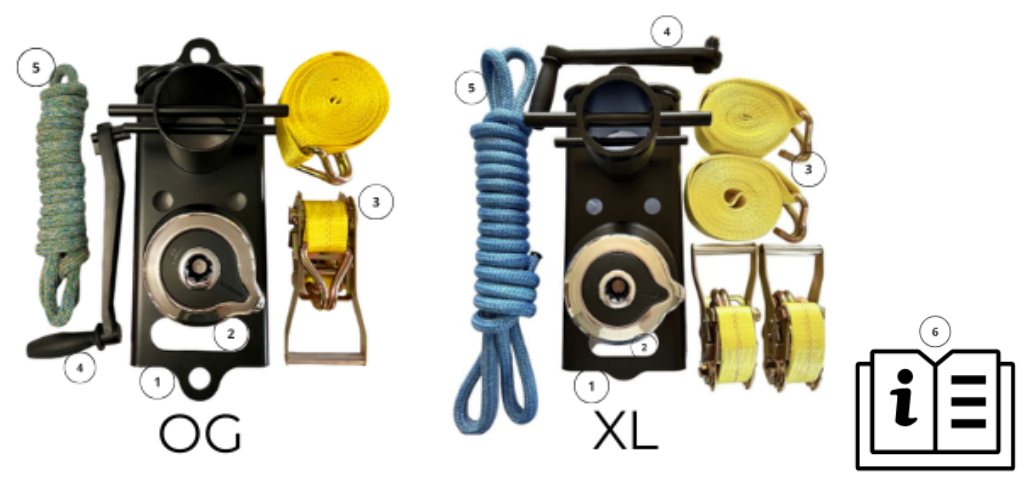
Package contents
Your HOLD FAST rigging system will include the following items (assembly included):
| # | Hold Fast OG | Hold Fast XL |
|---|---|---|
| 1 | Rigging plate / bollard | Rigging plate / bollard |
| 2 | Harken Radial 20 ST Winch | Harken Radial 40 ST Winch |
| 3 | 1 Ratchet strap (3,000 lbs WLL) | 2 Ratchet straps (3,000 lbs WLL each) |
| 4 | Winch handle | Winch handle |
| 5 | Anchor sling, 16 strand, 16 ft | Anchor sling, 5/8", 18 ft |
| 6 | Instruction manual | Safety & Operating Instructions |
Parts identification
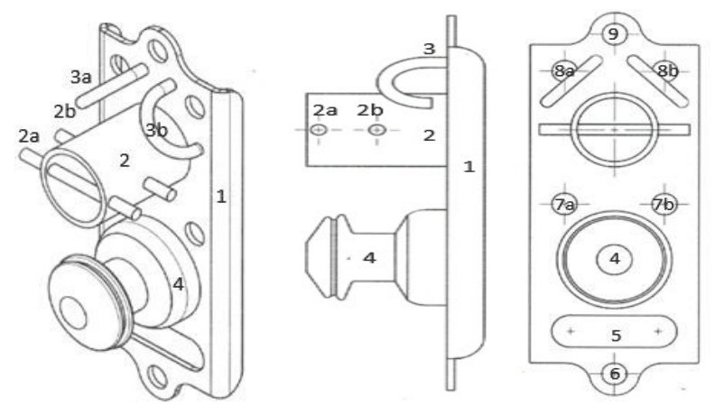
| # | Component | Notes |
|---|---|---|
| 1 | Rigging plate | Main structural plate |
| 2 | Rigging bollard | 2a: front post · 2b: rear post |
| 3 | Fairleads | 3a: bollard fairlead · 3b: winch fairlead |
| 4 | Harken Radial self-tailing winch | OG: Radial 20 · XL: Radial 40 |
| 5 | Hand port | Carrying handle for OG, and primary anchor attachment point for XL (for 5/8" anchor sling) |
| 6 | Basal anchor port (OG) | Omitted on XL |
| 7 | Ratchet strap anchor ports | 7a and 7b, and an additional 5 for XL |
| 8 | Additional accessory ports | 8a and 8b |
| 9 | Accessory carabiner port | For approved rigging accessories |
Harken Radial self-tailing winch
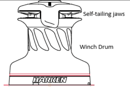
Technical characteristics
| Model | Speed | Power ratio |
|---|---|---|
| Hold Fast OG | 1-speed (Radial 20) | 19.2:1 |
| Hold Fast XL | 2-speed (Radial 40) | 13.5:1 & 39.9:1 |
Maximum working load limits
The Hold Fast working load limits have been independently established. The following values represent the maximum loads rated for these systems:
| Winch model | Working Load Limit (WLL) |
|---|---|
| Harken Radial 20 ST (Hold Fast OG) | 950 lbs |
| Harken Radial 40 ST (Hold Fast XL) | 1,500 lbs |
The maximum working load (MWL) for the 20 ST Radial Winch is 1,213 lbs (550 kg), and the MWL for the 40 ST Radial Winch is 1,874 lbs (850 kg). Subjecting the winch to loads above the WLL can cause the winch to fail suddenly and unexpectedly during high-load events, causing severe injury or death. These MWL figures are Harken's ratings for the winch as a component. The Working Load Limits published for the HOLD FAST system (950 lbs OG / 1,500 lbs XL) are lower, and are the limits you must rig to. Always work to the lowest rated component in the system.
Compatible winch line diameters
Harken Radial self-tailing winches have jaws preloaded with springs that adapt automatically to the following line diameters:
| Minimum rope diameter | Maximum rope diameter |
|---|---|
| 6 mm (1/4") | 12.7 mm (1/2") |
Use only line of a diameter between the limits listed above. DO NOT use wire rope, chain, or line not approved for arboriculture/marine use. To avoid accidents, carefully read, understand, and follow all warnings and instructions in the Harken Catalogue at www.harken.com.
Winch care & lubrication
Operating precautions
Using the winch demands important precautions: do not use Harken winches if you are not sufficiently trained and experienced in the general use of self-tailing winches.
- Keep your fingers, hands, loose clothing, gloves, and tools away from moving parts. In particular, avoid them entering between the line and the winch.
- Before using the winch, ensure all people and objects are clear of the movement of the reacting components of the system.
- Take particular care when releasing the line under load.
- If the winch is not in use, remove the handle and place it in a safe location outside the work zone.
- Do not apply a load greater than the maximum working load of the winch.
- Winches must be visually inspected at the beginning and end of each use.
- Winches must be completely overhauled, cleaned, and lubricated at least every 6 months. After inspection, replace any worn or damaged components. Refer to the Harken Radial Winch Maintenance Manual.
- Warning! Periodic maintenance must be carried out on a regular basis. Lack of adequate maintenance shortens the life of the winch.
Basic cleaning instructions
For assembly and disassembly, refer to the Harken Radial Winch Maintenance Manual.
- Wash winches frequently with fresh water, always after each use.
- Warning! Use a soft cloth for all cleaning and polishing operations. Do not use abrasive cloths on any component.
- Clean the bronze components and the anodized aluminum drums with a solution of water and vinegar (1 part vinegar + 2 parts water).
- Ensure the holes and drainage channels in the base of the winch are not obstructed so that water and debris do not collect.
Basic inspection & lubrication
For assembly and disassembly, refer to the Harken Radial Winch Maintenance Manual.
- Once the winch is completely disassembled, clean the parts with a degreasing agent that does not leave residues and is appropriate for metal components. Rinse plastic parts in fresh water.
- Dry all parts with lint-free cloths.
- Inspect gears, bearings, pins, and pawls for any signs of wear or corrosion.
- Carefully check the teeth of gears and ring gears to ensure there are no traces of wear.
- Check roller bearings to ensure there are no breaks in the bearing cages.
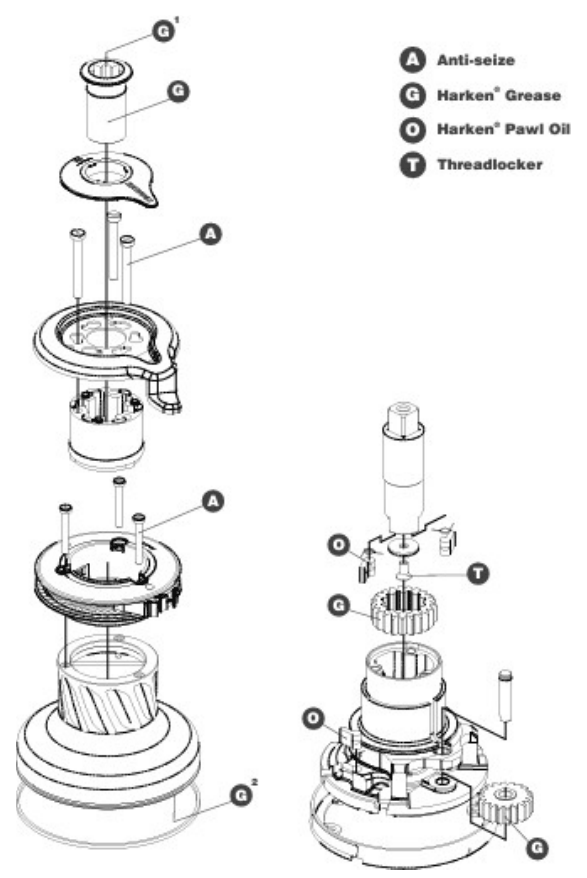
- Use a brush to lightly lubricate all gears, gear pins, teeth, and all moving parts with grease. Lightly lubricate pawls and springs with oil only. DO NOT use grease on the pawls!
Exploded view diagram
Exploded view with recommended maintenance products. Refer to the Harken Radial Winch Maintenance Manual for additional instructions and parts guide.
Stem mounting
The WLL is based on using a sufficiently rated anchor sling attached to the designated anchor point(s). The ratchet strap is designed for vertical positioning ONLY and should NEVER be used alone as a mounting strategy.
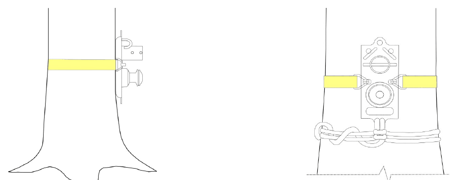
- When selecting the mounting location, choose an area where there is little or no stem taper. If the tree is to be removed, this can be achieved by shaping the stem prior to mounting.
- Never mount around the base/root flare of the tree. This can result in vertical slippage when load is applied.
- Install ratchet strap around the stem of the tree (Step 1) and terminate the hooked end in anchor ports (7a, 7b). A second ratchet strap can be installed in anchor ports (8a, 8b) if desired. Ensure hooks are facing toward the tree, fed correctly through the ratchet handle. Tighten the ratchet system as snugly as possible.
- Once securely mounted, attach an appropriately rated anchor sling (Step 2) to either the Basal Anchor Port (6) for up to 9/16" diameter line, or through the Hand Port (5) for XL, or if using a larger diameter sling.
- Ensure the sling is of sufficient length to terminate the hitch properly.
NEVER USE THIS DEVICE WITHOUT THE ANCHOR SLING ATTACHED. The anchor sling is the primary load-bearing attachment for the system.
Horizontal anchoring
The HOLD FAST rigging system is unique in that it can be rigged in the horizontal position.
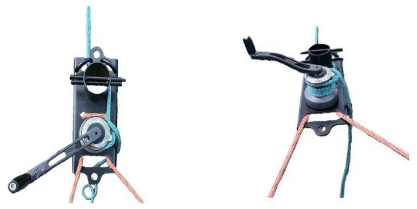
Mounting instructions
- For horizontal anchoring to be successful, you must have at least 2 anchors positioned approximately 45 degrees from the Basal Anchor Port (6). This allows for a triangular force to be applied to the rigging system when brought under load.
- Run a rated sling/rigging line from an appropriately rated anchor through the Hand Port (5), under the rigging plate, up through Anchor Port (7a), across the top of the rigging plate, and down through Anchor Port (7b), again running the line behind the rigging plate to emerge out of the Hand Port (5). Terminate the end of the sling/line at the second anchor.
- Run the rigging line through the fairlead and feed line clockwise around the self-tailing winch drum.
- Rotate the winch handle counter-clockwise to tension the rigging line.
- Tension the rigging line to desired tension.
The wider your anchoring positions are in relation to the Basal Anchor Port (6), or Hand Port (5) for XL, the more stable your horizontal rigging platform will be.
Rope routing: bollard
The following instructions demonstrate the correct routing of the working line(s) for the HOLD FAST rigging system. Never use alternative routing. This may result in injury or death.
The HOLD FAST rigging system allows for the use of multiple working lines simultaneously.
Rope routing to bollard
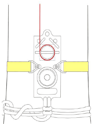
- Ensure the working line enters beneath the rigging bollard fairlead (3a or 3b) from a vertical point directly above the device.
- If NOT utilizing the winch, the working line can enter beneath either bollard fairlead (3a or 3b).
- Pass the rope behind the rear bollard post (2b).
- Pull the rope tight and continue with further wraps between the rear (2b) and front (2a) bollard posts.
- Apply the appropriate number of wraps around the bollard (2), based on the size/weight of the load being lowered.
- To suspend/lock off a load: wrap the working line a minimum of 4 times around the bollard and finish by applying a cleat hitch on the front bollard post (2a).
Once you are in a position to commence lowering, stand clear of the drop zone, ensuring the working line will not be obstructed by the load being lowered.
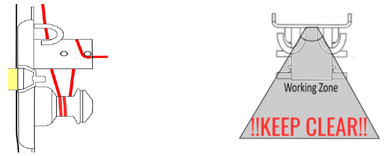
Rigging working zone: keep clear
- ALWAYS keep body parts, loose clothing, and debris away from the device when in use.
- ALWAYS remain outside of the Bollard Working Zone, the zone in which all lines feed through fairleads, bollards, and winch while in operation.
- ALWAYS maintain working line load pressure on bollard posts while engaged in lowering operations. This allows the user to remain at a safe distance from the device while lowering rigged pieces.
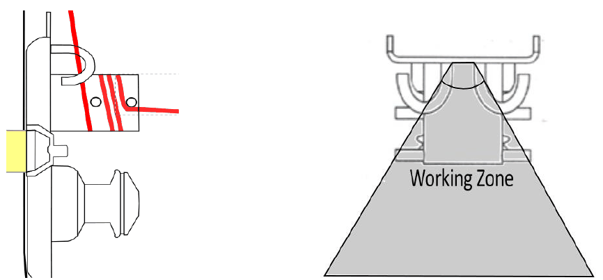
Position yourself, body parts, loose clothing, and loose hair OUTSIDE the Rigging Working Zone at all times. Doing so also ensures correct rope alignment, greatly reducing the chance of wraps overlapping or unspooling during lowering operations. Uncontrolled falling loads can cause extreme injury or death. Any person using this equipment should be fully trained and competent in its use before carrying out any rigging operations.
Rope routing: self-tailing winch
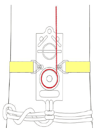
- Ensure the working line enters beneath the rigging bollard fairlead (3b) from a vertical point directly above the device.
- Pass the rope behind the rear bollard post (2b) and toward the winch (4) positioned below the bollard.
- Take at least 3 turns (clockwise) around the winch drum (4) in the direction the winch rotates. For high loads, take an additional turn.
- Pull rope taut. To ensure correct functioning of the self-tailing mechanism, the number of turns taken around the drum must NOT hamper the movement of the lower self-tailing jaw.
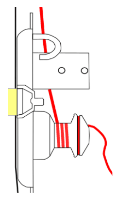
- The more turns taken around the winch drum (4), the lower the load the operator has to handle.
- DO NOT take turns around the base of the winch drum.
- Position the working line over the self-tailing arm and take another turn positioning the line in the self-tailing jaws. The jaws will automatically adjust to the size of line being used. Harken recommends 1/4"–1/2" line for the Radial winch. Do not exceed the recommended diameter for optimal self-tailing performance.
- At this point the working line is locked off.
- Insert the winch handle into the head of the winch. Begin tensioning the working line by rotating the handle counter-clockwise.
- Take particular care while releasing the line under load!
DO NOT STAND UNDER THE LOAD AT ANY TIME DURING RIGGING OPERATIONS.
Removing line from self-tailing jaws
- To remove wraps: place the palm of your hand carefully on the winch drum to maintain rope/drum pressure and carefully remove one turn at a time until the load begins to move freely on the winch drum. Be particularly mindful of keeping fingers clear of line wraps and the winch drum.
- Before lowering the load, maintain control over the load from a distance by capturing the line on the bollard. Take a half turn around the forward bollard post (2a) and position yourself outside of the Working Zone. This ensures you remain clear of pieces under load and maintains correct rope alignment on the winch drum as wraps move freely when tension is released.
Position yourself, body parts, loose clothing, and loose hair OUTSIDE the Rigging Working Zone. Uncontrolled falling loads can cause extreme injury or death. Any person using this equipment should be fully trained and competent in its use before carrying out any rigging operations.
Double working lines
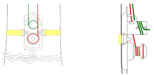
- Ensure working lines enter beneath the rigging bollard fairleads (3a, 3b) from a vertical point directly above the device.
- Pass the line intended for the bollard through bollard fairlead (3a). Pass the line intended for the self-tailing winch through fairlead (3b).
- Pass the bollard line (green) between the front and rear bollard posts. This ensures available space for the self-tailing line (red) behind the rear bollard post. Continue with the bollard routing instructions in section 10 to complete the correct routing and operation sequence.
- Pass the winch line (red) behind the rear bollard post (2b). Continue with the self-tailing winch routing instructions in section 11 to complete the correct routing and operation sequence.
It is important while operating multiple lines to maintain separation between the bollard working line and the self-tailing winch working line. Line isolation is especially important while the rigging system is under load. Damage to both working lines will occur if care is not taken to ensure proper line routing through the system. Before applying any load to either line ensure that both working lines are appropriately isolated in the rigging system. Damaged working lines can lead to unexpected failure of one or both load bearing lines. Uncontrolled falling loads can cause extreme injury or death.
The user should position self, body parts, loose clothing, loose hair, etc. OUTSIDE of the Rigging Working Zone. By positioning oneself outside of this zone it also ensures correct rope alignment, greatly reducing the chance for wraps overlapping or unspooling during lowering operations contributing to the uncontrolled descent of the load. Uncontrolled falling loads can cause extreme injury or death. Any person using this equipment should be fully trained and competent in its use before carrying out any rigging operations.
Accessories & bollard care
Accessory carabiner port (9)
The HOLD FAST rigging plate allows space for the quick addition of rigging accessories to the system. For a list of approved accessory tools, please contact the manufacturer or visit holdfast-rigging.com.
Bollard care
Your HOLD FAST Rigging System is fully powder coated except for a 3" strip between the two horizontal bollard posts. This is to ensure that your ropes remain free from melting to the bollard during high-friction rigging scenarios. The exposed metal has been acid washed, gun blued, and sealed to resist corrosion.
A simple application of gun bluing agent and/or a light oiling is all that is needed to maintain a sleek, gun barrel appearance.
To protect the finish during shipping, the exposed section has been lightly coated with oil and wrapped in plastic. Before first use, simply wipe off any excess oil from the exposed metal surface.
Support & service policy
Hold Fast Rigging Systems are engineered, tested and supported for professional rigging environments. The following outlines our approach to performance, inspection responsibility, replacement parts, returns, and eligibility for service support.
Performance & load ratings
Hold Fast Rigging Systems, including the Hold Fast OG and Hold Fast XL, are field tested and break tested well beyond their published working load limits. Published ratings are intentionally conservative to support safe rigging practices and to preserve meaningful operational safety margins under real-world conditions. Operators should always rig to published working load limits, never to tested failure points.
Inspection responsibility
All Hold Fast systems and components should be inspected before each use. Any equipment showing damage, deformation, corrosion, excessive wear or signs of improper use must be removed from service immediately and evaluated before returning to operation. Inspection records are the responsibility of the owner or operator.
Replacement parts & service support
Replacement components and service support are available for many wear items and hardware components across the Hold Fast product line. Customers and dealers may contact Hold Fast Rigging directly for current availability, lead times and support options. Harken winch components integrated into Hold Fast systems are supported through Harken's published service documentation and parts catalog; pricing on Harken components is subject to update through their distribution channels.
Return policy
Unused and unmounted systems may be returned within 15 days of delivery in original, resalable condition with all original packaging and documentation. The customer is responsible for return shipping unless otherwise approved in writing. Returns are processed once the equipment has been received and inspected.
Conditions affecting eligibility
Equipment subjected to any of the following is not eligible for return or replacement consideration:
- Shock loading or overloading beyond published working load limits
- Modification, alteration, or substitution of components
- Improper mounting, installation, or integration
- Misuse, neglect, or operation outside published guidelines
- Damage from environmental exposure inconsistent with intended use
Service support, replacement parts, or return authorization: 317-435-0392 · sales@holdfast-rigging.com · holdfast-rigging.com
Records & inspection log
Product record
Complete at time of purchase and retain for the life of the unit:
Inspection & maintenance log
Inspections must be performed by a competent person whose training meets the applicable standards and laws for the inspection of life safety equipment. A detailed inspection is required at least every 12 months, and after any shock load or loading above the WLL. Keep the log as a permanent record for the life of the unit.
Each entry records: date, findings & condition, pass / fail, and the inspector's name & signature. A printable log sheet is on page 23 of the PDF manual. Photocopy it as needed.
↑ Back to contents